Designing with Continuous Insulation for Thermal and Moisture Management
5 Min Read April 10, 2018
Building codes and green building standards continue to raise the bar on energy efficiency and high performance in buildings. In wood-framed buildings, addressing both insulation levels and air tightness in the building enclosure continue to be refined by code and elective program standards. While this is a positive trend, determining the best amount and type of exterior continuous insulation can be challenging.
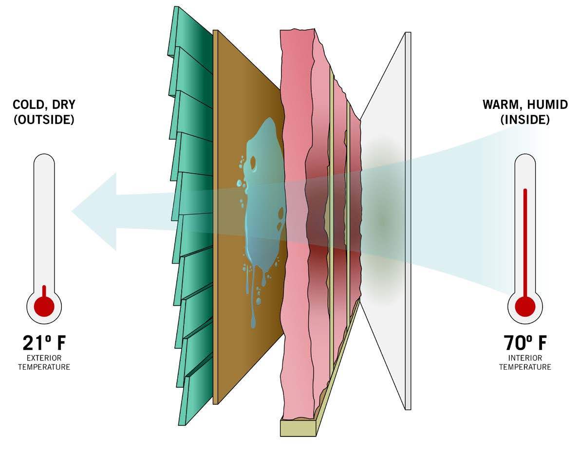
Codes suggest different amounts of continuous insulation for different climate zones. There is also concern that continuous insulation can impact the ability of the wall to “breathe” and release any trapped moisture from within the wall assembly so, in some cases, it can impact the choice of an interior vapor retarder on the warm, inner side of the building. All of these variables and options have led to some significant confusion concerning the best way to properly address both code required thermal insulation and manage vapor in wall assemblies. The “Designing with Continuous Insulation for Thermal and Moisture Management” CEU course available on Hanley Wood University helps provide clarity on the differences between the varied prescriptive code requirements for continuous insulation in different climate zones along with principles and choices related to proper moisture management. Here’s a glance at some of the topics covered.
Heat transfer

Framed wall construction, whether using wood studs or metal studs, has an inherent weakness from a thermal efficiency point of view. Simply put, the framing allows more heat to flow through it than insulation does and heat always seeks a balance by flowing from a warm source to a cooler place. In buildings, heat transfer is based on U-factors, which indicate how much energy passes through material over time for each degree in temperature difference. (The greater the temperature variance in the two sides of the material, the more intensely the heat flows.) U-factor is determined by testing that material on a square foot basis over time while measuring the temperature difference between the two sides. The resulting number is generally a decimal (e.g., 0.5) with smaller numbers indicating small amounts of heat transfer (think insulation) and higher numbers indicating more heat transfer (think conductive metal). Applying this to a building, the fundamental formula used is (U x A) x dT where U = the tested U-factor for one square foot of material, A = the area in square feet installed in a construction assembly, and dT is the design or actual temperature difference between indoors and outdoors. All thermal energy calculations in building enclosures (e.g., walls, roofs, etc.) are based on this fundamental formula.
Thermal Bridging
Construction assemblies are very rarely monolithic. Rather, they require different materials that are assembled to make up the overall construction. In typical situations, the framing can account for 20-30 percent of the area of any given exterior wall with only about 70-80 percent of the wall area actually containing insulation. Since the framed sections will not have the same U-factor/R-value of the insulation, the thermal effectiveness of the wall is directly compromised. It is easy to ask: Is this 20-30 percent framing area really a big deal? It turns out that the answer is yes. Any building material, including framing or sheathing, that has a capacity to transfer heat more than insulation will follow the laws of physics and do so. In this case, every stud or other solid structural item like floor band joists, columns, etc., is acting as a breach in the insulated wall, allowing heat to transfer through it. The solid connection between the warm side and the cool side of an assembly acts as a “thermal bridge” and allows heat to flow freely between the sections where the insulation is present.
Continuous Insulation Choices

A solution to all of these thermal bridges can be continuous insulation. A variety of insulated sheathing products have become available over the past few decades. In framed walls, there is also the need for solid sheathing over the studs that can provide structural bracing for the wall and a durable nailbase for the attachment of siding, cladding, brick ties, etc. Many exterior insulation products are rated to be structural and don’t necessarily provide a good nail base. That usually means the continuous insulation is put up after structural sheathing goes over the studs. In many cases, another layer is needed to provide a nail base or else the exterior cladding needs to be carefully attached to the studs. This multistep process can add to the labor involved and the detailed design of multiple layers.
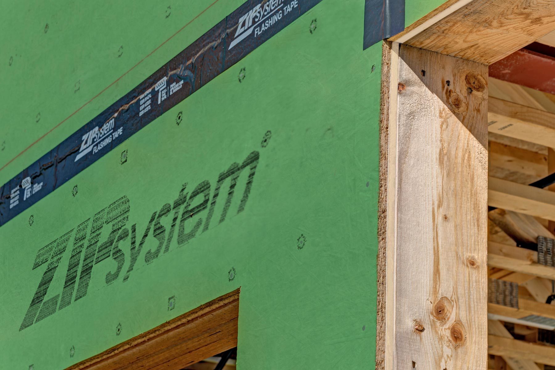
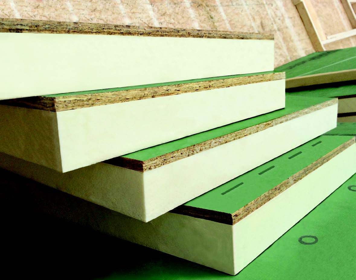
Design and construction teams are turning to a streamlined approach to incorporate continuous insulation with an engineered wood system that not only solves for a structural, nailable exterior outside of continuous insulation, but also eliminates the need for housewrap. ZIP System® R-sheathing is a next-generation engineered wood sheathing system with a built-in water-resistive barrier, rigid air barrier and integrated polyisocyanurate continuous foam insulation on the backside of the panel. Completed with taped panel seams, the system helps create a tight exterior envelope with optimal permeance that allows panels to drive to the outside. ZIP System R-sheathing is available with multiple insulation thicknesses from ½” to 2” to meet needs in all climate zones. Learn more at ZIPSystem.com/R-sheathing.

